Computed Tomography (CT)
Agenda
- Introduction
- CT Vs. Conventional Radiography
- Generations of CT Scanner (1st - 4th)
- Component of CT scan
- Gantry
- X-ray tube
- Detectors
- Data Acquisition System
- Stationary computer
- CT Images Forming
- Couch
- Fifth generation: Electron-beam computed tomography (EBCT)
- Dynamic Spatial Reconstructor (DSR)
- Scan modes
- Axial
- Helical (Sixth Generation)
- Pitch
- Seventh Generation of CT (Multidetector /Multislice /Multirow CT)
- PIXEL & VOXEL
- Advantages and Risks
Introduction
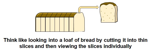
- The word tomography is derived from Greek, tomos (slice) and graphein (to write).
- Computed Tomography (CT) imaging, also known as "CAT scanning" (Computed Axial Tomography).
- Was developed in the early to mid 1970s and is now available at over 30,000 locations throughout the world.
- CT is fast, patient friendly and has the unique ability to image a combination of soft tissue, bone, and blood vessels.
- Since its invention, CT imaging has seen massive advances in technology and clinical performance.
- Today CT enables the diagnosis of a wider array of illness and injury than ever before.
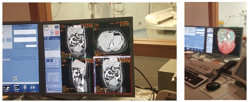
- Computed tomography scan machines uses X-ray.
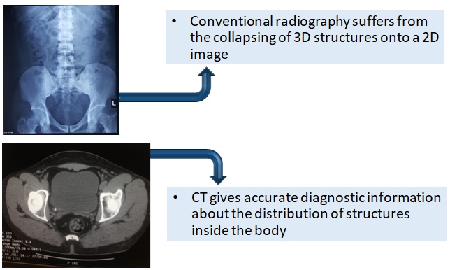
- CT combines X radiation and radiation detectors coupled with a computer to create cross sectional image of any part of the body.
CT Vs. Conventional Radiography
Generations of CT Scanner
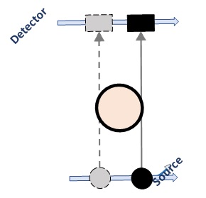
First generation
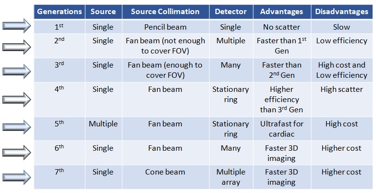
- Narrow pencil beam
- Single detector per slice
- Translate – rotate movements of tube-detector combination
- Scan time: 5 minutes
- Designed only for evaluation of brain, axis of rotation passed through the center of the patients head
- Over night image reconstruction
Second generation
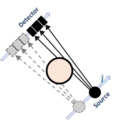
- Narrow fan beam(3o-10o)
- Linear detector array(30)
- Translate-Rotate movements of Tube-Detector combination
- Fewer linear movements are needed as there are more detectors to gather the data
- Between linear movements, the gantry rotated 30o
- Only 6 times the linear movements got repeated
- Scan time: ~20secs
Third generation
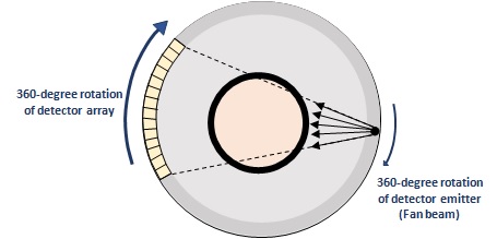
- Rotate(tube)-rotate(detectors) Translatory motion is completely eliminated
- Pulsed wide fan beam (500-550)
- Arc of detectors ( 600-900)
- Detectors are perfectly aligned with the x-ray tube
- Both xenon and scintillation crystal detectors can be used
- Scan time < 5sec
Fourth generation
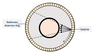
- Continuous wide fan beam (500-550)
- Ring of detectors(> 2000)
- CT systems employ a stationary detector ring and a rotating x-ray tube. Rotate(tube)-Fixed(detector)
- The anatomy to be scanned is placed within the circle of detectors
- Scan time < 2sec
Component of CT scan
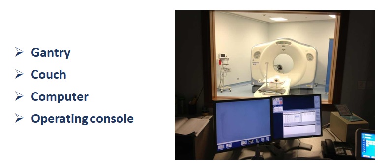
Gantry
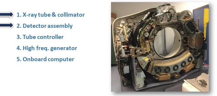
The gantry assembly is the largest of these systems. It is made up of all the equipment.
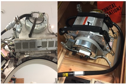
X-Ray Tube
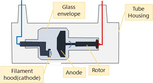
- The X-ray tube is a special type of vacuum-sealed, electrical diode that is designed to emit x rays. It is made up of two electrodes, the cathode (-) and anode (+).
- To produce X-rays, a filament in the cathode is charged with electricity from a high voltage generator. This causes the filament to heat up and emit electrons. Using their natural attraction and a special focusing cup, the electrons travel directly toward the positively charged anode.
- X-rays are emitted indiscriminately when the electrons strike the anode. The anode, which can be rotating or not, then conducts the electricity back to the high-voltage generator to complete the circuit. To focus the X-rays into a beam, the X-ray tube is contained inside a protective housing.
X-ray Tube Housing
Decreases leakage radiation to maximum level of 100 mR/hour at a distance of 1 meter
- Minimizes exposure dose to patient and radiographer
Provides mechanical support for x-ray tube
Oil circulates around x-ray tube
- Insulator protecting from electric shock
- Dissipates heat
- Cooling fan
Detectors
- The detectors in a CAT scanner measure radiation attenuated from the body structures due to their interaction with X-rays. Capture energy that has not been attenuated by the patient.
- Detectors Made up of multiple discrete cells or detectors.
Two types of detectors are used:
- Crystal Scintillation Detectors (Solid State Detectors) :
- Photodiode
- Photomultiplier Tubes
- Gas Filled Detectors
The detector array of more modern scanners uses tungsten plates, a ceramic substrate, and xenon gas.
Scintillation Detectors with photodiode (Crystal)
- Crystal converts incident x-rays to light
- Photodiode semiconductor current proportional to light
Coupled optically to photodiode
Materials Used:
- Calcium tungstate
- Sodium Iodide
- Bismuth Germanium Oxide
- Cesium Iodide
- Calcium tungstate + SI Photodiode (more frequent)
- Scintillation crystal detector used in III and IV gen. CT scanners
.jpg)
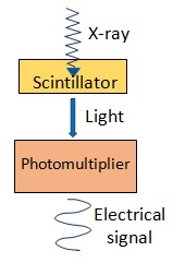
Scintillation crystals used with pm tubes
- X-ray energy converted to light
- Light converted to electrical signal
- Sodium Iodide – afterglow+ Hygroscopic+ Low dynamic range (used in the past)
- Calcium fluoride
- Cesium iodide(Csl)
- Bismuth geremanate
- Short decay time-afterglow not a problem
Scintillation crystal detector (PM Tube) used in I & II gen. CT scanners
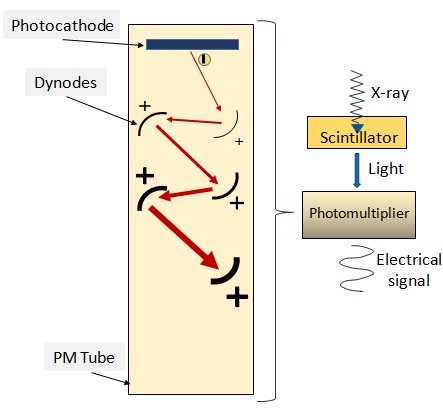
Photomultiplier Tubes
- Light incident on Photocathode of PM tube
- Photocathode releases electrons
- Electrons attracted to series of dynodes
- Each dynode slightly more positive than last one
Gas Filled Detectors
- Ideal gas-filled detector is made by placing strips of tungsten 0.04 inch (1 mm) apart around a large metallic frame. A ceramic substrate holds the strips in place. The entire assembly is hermetically sealed and pressure filled with an inert gas such as xenon.
- Each of the tiny chambers formed by the gaps between the tungsten plates are individual detectors. The finished detector is also attached to the scanner frame.
- Have high atomic number, are inert, and display minimal afterglow.
- The gas is contained under high pressure in the detector array

Data Acquisition System
The DAS consists of the following parts:

- X-ray photons come on the detector.
- The detector detects the intensity in form of current.
- The current is converted into voltage.
- The analog integrator removes spikes.
- The analog signal is converted into digital form.
- This signal can now be processed and reconstructed in the computer.
Stationary computer
- The computer is specially designed to collect and analyze input from the detector.
- It is a large capacity computer capable of performing thousands of equations simultaneously.
- The reconstruction speed and image quality are all dependent on the computers microprocessor and internal memory.
CT Images Forming
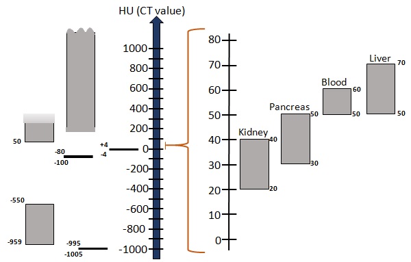
- The average linear attenuation coefficient, μ ,between tube and detectors
- Attenuation coefficient reflects the degree to which the x-ray intensity is reduced by a material
- μ values are scaled to that of water to give the CT number
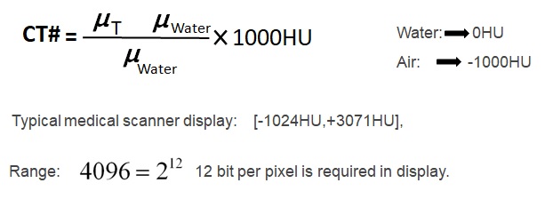
CT numbers & Gray scale
COUCH
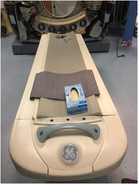
- The patient lies on the couch (also known as a table) and is moved through the CT gantry aperture during the CT examination. Depending on the body part to be scanned and the protocol selected the patient may be positioned supine or prone and either head or feet first.
- A weight limit for the couch of approximately 205kg (450lb) is specified by the manufacturer.
- During conventional slice-by-slice scanning the couch is indexed (moved) between each scan depending on the slice thickness and slice incrementation (degree of overlap or separation) that has been selected for that examination.
- Spiral/Helical CT, including multislice CT the couch is translated through the gantry at a constant speed depending on the length of the area to be scanned, the total scan time, and the pitch that has been selected.
Other scan configurations
Interest in faster scan times evolves from a desire to image moving structures such as, the wall of the heart and contrast material in blood vessel and heart chambers and to overcome motion artifacts due to cardiac rhythm and patient breathing
- Electron beam computed tomography
- Dynamic Spatial Reconstructor(DSR)
Fifth generation
Electron-beam computed tomography (EBCT)
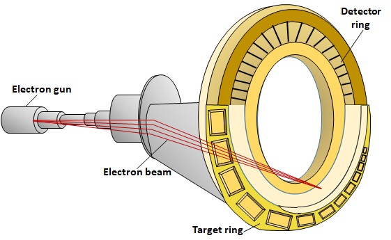
- EBCT does not use an X-ray tube; instead it uses a beam of electrons generated outside the gantry.
- Inside the gantry there are 180-degree rows of fixed detectors on one side and 180 degrees of tungsten arcs opposite. The electron beam is rapidly moved to bombard the tungsten arcs, producing an x-ray beam.
- The x-rays then pass through the patient and transmission information is collected by the detectors. These units are very fast because they have no moving parts.
- For a number of years they were the only scanners fast enough for cardiac imaging. However, two additional developments resulted in significant scan time reduction and minimized the use of EBCTs.
- Developed for cardiac imaging, the EBCT reduces scan time to as little as 50 ms, fast enough to image the beating heart.
Dynamic Spatial Reconstructor (DSR)
- The Dynamic Spatial Reconstructor (DSR) is a high-temporal resolution, three-dimensional (3D) X-ray scanning device based on computed tomography (CT) principles
- An experimental apparatus
- 28 X-ray tubes
- X-ray tubes are aligned with 28 light amplifiers and TV cameras that are placed behind a single curved fluorescent screen
- The gantry rotates about the patient at a rate of 50 RPM
- Data for an image acquired in about 16 ms.
- Disadvantages:
- High Cost
- Mechanical motion is not eliminated
.jpg)
Scan modes
- Once the patient is on the table and the table is moved into the gantry, the technologist performs a preliminary scan called the CT radiograph. CT systems can scan anterior-posterior (AP), posterior-anterior (PA), or lateral.
There are 2 common scan modes:
Axial
Helical
Axial
- The axial (also called sequential) CT scan is the basic step-and-shoot mode of a CT scanner. The gantry rotates at typical rotation speeds of 0.5 s, but the x-ray tube is not turned on all the time.
- The table is stationary during the axial data acquisition sequences. The system acquires 360 degrees of projection data with the x-ray tube activated, the tube is deactivated, the table is moved with the X-ray beam off, another scan is acquired, and so on.
- This process is repeated until the entire anatomical area is covered. Because the table and patient are stationary during an axial scan, the X-ray tube trajectory defines a perfect circle around the patient. Due to the tables start/stop sequence.
Helical (Sixth Generation)
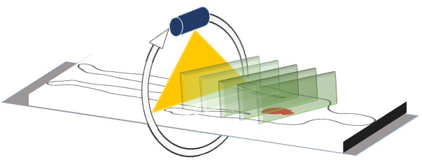
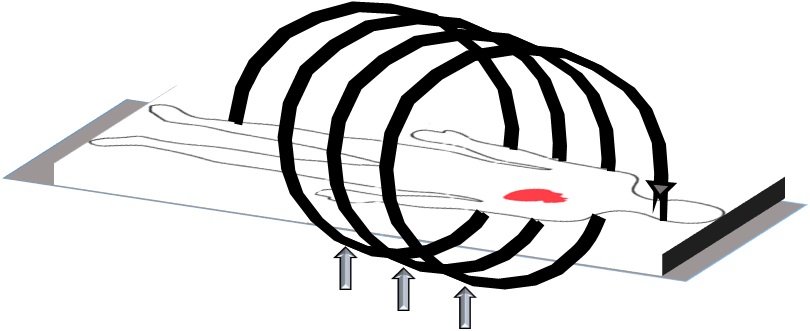
- The helical (also called spiral) scanning, the table moves at a constant speed while the gantry rotates around the patient. This geometry results in the X-ray source forming a helix around the patient.
- The advantage of helical scanning is speed—by eliminating the start/stop motion of the table as in axial CT, there are no inertial constraints to the procedure. Similar to the threads on a screw, the pitch describes the relative advancement of the CT table per rotation of the gantry.
Three technological developments:
- Slip-ring gantry designs
- Very high power x-ray tubes
- Interpolation algorithms to handle projection data
.jpg)
Pitch
- Pitch (P) is a term used in helical CT. It has two terminologies depending on whether single slice or multislice CT scanners are used.
Single slice CT (SSCT)
The term detector pitch is used and is defined as table distance traveled in one 360° gantry rotation divided by beam collimation.
For example, if the table traveled 5 mm in one rotation and the beam collimation was 5 mm then pitch equals 5 mm / 5 mm = 1.0.
Multislice CT (MSCT)
Beam pitch is defined as table distance traveled in one 360° gantry rotation divided by total thickness of all simultaneously acquired slices.
Choice of pitch affects both image quality and patient dose:
- P = 1.0: x-ray beams are contiguous for adjacent rotations
- P >1.0: x-ray beams are not contiguous for adjacent rotations, i.e. there are gaps in between the x-ray beams and tissue is not irradiated
- P <1.0: there is x-ray beam overlap; i.e. a volume of tissue is irradiated more than once per scan. Thus a pitch >1.0 results in decreased patient dose but also decreased image quality (through fewer projections obtained, resulting in lower SNR). A pitch of <1.0 results in better image quality, but a higher patient dose.
Slice thickness
Thinner slices mean
- Less scatter
- Better contrast
- Less active detector area
- Less photons detected
- More noise
- To achieve equivalent noise with thinner slice, dose(technique factors) must be increased

Seventh Generation of CT
Multidetector /Multislice /Multirow CT
- Most recent advancement, introduced in 1998.
- In 2000, 8 slice CT were presented, followed by 16 slice in 2001
- This uses usually 64-128 adjacent multiple detector arrays in conjunction with a helical CT scanner , the collimator spacing is wider and more of the x-rays that are produced by the tube are used in producing image data.
- Scanning time: 0.25 second
- The collimator spacing is wider and more of the x-rays that are produced by the tube are used in producing image data
Opening up the collimator in a single array scanner increases slice thickness, reducing spatial resolution in the slice thickness dimension
With multiple detector array scanners, slice thickness is determined by detector size, not by the collimator
PIXEL & VOXEL
- Cross sectional layer of the body is represented as an image matrix.
- Each square of the image matrix is called pixel(picture element) and it represents tiny block of tissue called voxel (volume element)
- The linear attenuation coefficient (µ) of each pixel is determined by:
- Composition of the voxel
- Thickness of the voxel µ
- Quality of the radiation beam
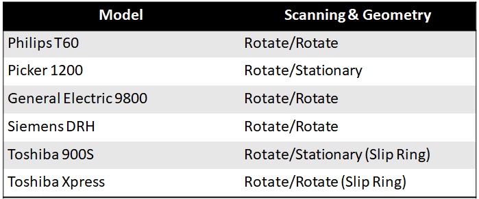
Compare Different Models
Advantages of CT scanning
- CT scanning is painless, noninvasive and accurate.
- A major advantage of CT is its ability to image bone, soft tissue and blood vessels all at the same time.
- Unlike conventional x-rays, CT scanning provides very detailed images of many types of tissue as well as the lungs, bones, and blood vessels.
- CT examinations are fast and simple; in emergency cases, they can reveal internal injuries and bleeding quickly enough to help save lives.
- CT has been shown to be a cost-effective imaging tool for a wide range of clinical problems.
- CT is less sensitive to patient movement than MRI.
- CT can be performed if you have an implanted medical device of any kind, unlike MRI.
- CT imaging provides real-time imaging.
- No radiation remains in a patients body after a CT examination.
Risks
- Because children are more sensitive to radiation, they should have a CT exam only if it is essential for making a diagnosis and should not have repeated CT exams unless absolutely necessary. CT scans in children should always be done with low-dose technique.
- The risk of serious allergic reaction to contrast materials that contain iodine is extremely rare, and radiology departments are well-equipped to deal with them.
- The effective radiation dose for this procedure varies.
- Women should always inform their physician and x-ray or CT technologist if there is any possibility that they are pregnant . CT scanning is, in general, not recommended for pregnant women unless medically necessary because of potential risk to the baby in the womb.