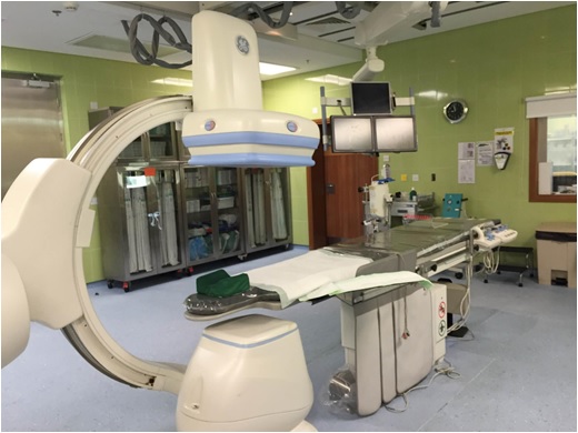
fluoroscopy System
What is a fluoroscopy?
- Fluoroscopy is a continuous X-ray image on a monitor (X-ray movie).
- By passing X-ray beams through the body, the movement of a body part or of an instrument or contrast agent can be seen in detail.
There are two main parameters, by adjusting them, X-ray/photon energy, X‐ray intensity and number of photon/X-ray can be control.
- Peak KiloVoltage ‐ kVp
- Increasing kVp is associated with worsening of low‐contrast detectability (see photon interactions as a function of photon energy)
- Tube Amperage ‐ mA
- Increasing mA is associated with the improvement of noise, low‐contrast detectability , and better statistics (more counts) in our image
Geometry
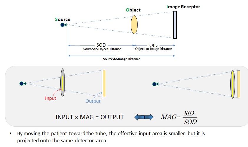
- The x‐ray field DIVERGES with increased distance from FS
- Field edge (L) increases proportionally with D
- Field area (A) increases proportionally with D2

- The intensity (X) of the x‐ray field decreases with D2
- Distance can really help or really hurt the situation

Bird’s Eye View and Magnification
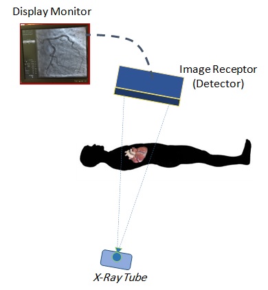
Fluoroscopy system Components
- X-ray Tube
- Image Receptor (Detector)
- Display Monitor
X-Ray Tube
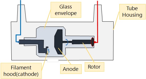
- The x-ray tube is a special type of vacuum-sealed, electrical diode that is designed to emit X-rays. It is made up of two electrodes, the cathode (-) and anode (+).
- To produce X-rays, a filament in the cathode is charged with electricity from a high voltage generator. This causes the filament to heat up and emit electrons. Using their natural attraction and a special focusing cup, the electrons travel directly toward the positively charged anode.
- X-rays are emitted indiscriminately when the electrons strike the anode. The anode, which can be rotating or not, then conducts the electricity back to the high-voltage generator to complete the circuit. To focus the X-rays into a beam, the X-ray tube is contained inside a protective housing.
X-ray Tube Housing
- Decreases leakage radiation to maximum level
- Minimizes exposure dose to patient and staff
- Provides mechanical support for X-ray tube
- Oil circulates around X-ray tube
- Insulator protecting from electric shock
- Dissipates heat
- Cooling fan
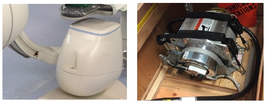
Receptors
Current fluoroscopy systems(receptors) fall into two distinct categories based on their receptors:
- Image intensifier
- Flat-panel detector (FPD)
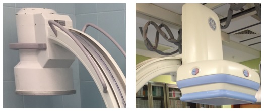
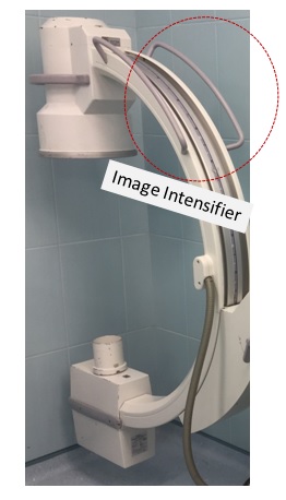
Image Intensifier Fluoroscopy Systems
- Soon after their development in the late 1950s, image intensifiers were coupled with television systems to enable viewing of fluoroscopic images.
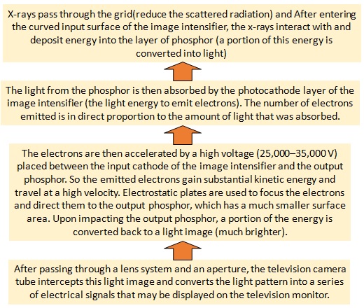
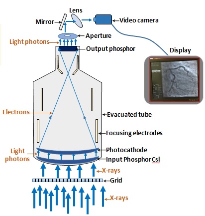
- It is a very large vacuum tube that captures the pattern of X-ray radiation transmitted through the patient and converts it into a light image of sufficient brightness to be seen on the television camera.
Schematic of internal structures of an image intensifier and its working principles
FPD Fluoroscopy Systems
- More modern solid-state detector arrays used as the image receptor.
- Better stability, lower patient radiation doses, and wider dynamic ranges in compare to image intensifier fluoroscopy systems.
- The FPD consists of an array of individual DELs (detector element) that may contain 1.5–5.0 million individual DELs.
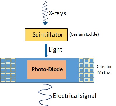
- Most FPD arrays are indirect solid-state systems (the x-ray energy is first converted to light and then to an electronic signal).
- An individual DEL consists of a scintillation layer (usually composed of CsI) and by attenuating the incident x-rays produces light.
- The CsI scintillation layer is composed of many needle-like crystals, which are grouped together to cover the surface of the DEL that help direct light toward the photodiode located below.
- The amount of light produced is directly related to the amount of x-ray flux that is incident on the DEL.
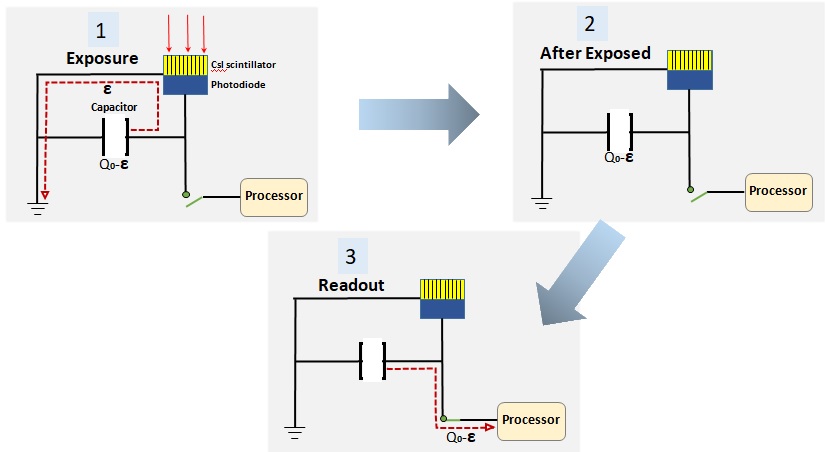
- When light hits the surface of the low-noise photodiode and transistor below, it acts like a switch, allowing the diode to conduct electricity. In the absence of light on its surface, the photodiode acts like an insulator, preventing the flow of electrons.
Block diagram shows how each DEL records the x-ray
Flat-panel detectors VS Image intensifier
FDP receptors have a number of advantages over image intensifier fluoroscopy systems including better stability, lower patient radiation doses, and wider dynamic ranges.
- Magnification Modes:
- However, each step up in magnification cause more detail becomes visible, decrease the field of view. For higher magnification the II needs to collimate down.
- Resolution:
- Overall, FPD systems have the capacity to produce clearer, sharper high-quality digital images than average II system.
- System Price:
- New FPD units costs around 2 to 3 times more than their II counterparts.